
Introduction
This month’s ResFrac release has a ton of new capabilities. The most important is called ‘multisector’ – the ability to split different sections of the well across different computers. This capability provides a computationally efficient and practical way to run larger models and handle complex scenarios.
Hats off to Danial Zeinabady and Michael Nole, who have been the main developers on this project. Beyond them, it’s been a big team effort, pulling in folks from cloud, simulator, and user-success.
First, let’s review – what is sector modeling? Why do we need a ‘multi’ version of it?
‘Sector’ modeling refers to simulating one or a few stages along each well, instead of the full well. Modern shale wells have 30-70 stages. For many practical applications, it is sufficient to model just one stage (or a few) and multiply simulated production to scale them up. Simulating a full lateral results in redundantly running a large number of similar simulations.
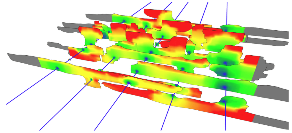
The image below shows a single-stage sector model. One stage is modeled for each of the five wells.
Why is it OK to not simulate every stage?
In most wells, each stage receives a similar stimulation design. Of course, the formation has heterogeneity, but we usually do not have enough geophysical resolution and accuracy to map that heterogeneity across the pad scale. Even if we did have information, we nearly always lack data to provide stage-by-stage production allocation, and so we could not validate or calibrate the model predictions of per-stage performance.
ResFrac is typically used to design an upcoming pad. To do so, we do not need to capture every detail of every stage from the prior pad – we need a calibrated model that can help us design the future pad. Thus, we focus on modeling a ‘typical’ stage in order to design a future ‘typical’ stage.
Stages are affected by their neighbors, but we can account for these effects with boundary conditions. We use ‘external fractures’ to account for stress shadow from prior stages, no-flow boundaries along the edge to account for production interference, and symmetric/no-displacement boundary conditions to address porothermoelastic stress effects.
Having said all that – there are situations where it is useful to simulate multiple stages, or even the full lateral. Common situations include: (a) wells where multiple different fracturing designs were used at different locations along the well, (b) partial offset from other wells, (c) situations with known heterogeneity, (d) situations where wells are not consistently landed in a single zone, and (e) Enhanced Geothermal Systems.
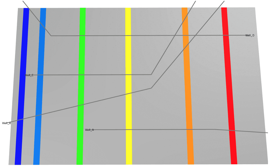
The picture below shows a complex scenario where multisector can be useful. Wells partially overlap and are even at an angle. There is no single ‘sector’ that can represent every stage in every well.
There the two types of multisector modeling – coupled and uncoupled. Both capabilities are described below.
Uncoupled multisector
The default option for multisector – which I expect to be the most commonly used – is called ‘uncoupled.’ In uncoupled modeling, multiple sector simulations are run independently from each other. They do not interact – they are independent simulations. But from the user’s perspective, they are treated as a single unified simulation – in both the setup and outputs.
This approach is well-suited for shale applications. Speedup is great because rather than simulating every fracturing stage one after the other, we can simulate each stage simultaneously by spreading the work across different computers. To account for the effect of neighboring stages, we use the same techniques that we use with single-sector simulations – appropriate selection of boundary conditions.
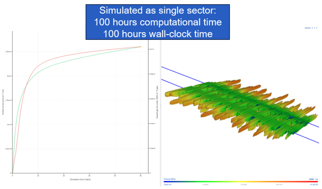
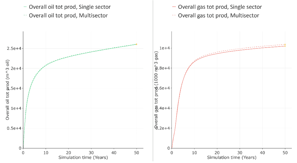
For example, the image below shows a ‘single sector’ simulation with 10 fracturing stages in two wells each, followed by production. The simulation used a fine mesh and ran on the smaller ‘4 core’ machine size, and so the simulation was slow – it took 100 hours of wallclock time.
Next, we reran this simulation as a ten sector multisector simulation (each using the same 4 core machine). Each of the sectors ran in one hour each. They ran simultaneously, and so the user received the answer in 1 hour instead of 100 hours – a 100x reduction in wallclock time. Each of the ten sectors ran on a separate computer, and so the CPU time was 10 hours – a 10x reduction.
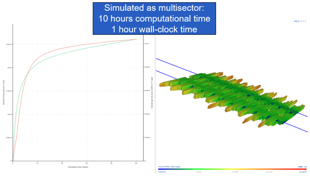
These are very large reductions in runtime and cost. Yet, comparing the simulations, the results are similar.
Another advantage of multisector is that it averages out random variance. In ResFrac, we incorporate a variety of random phenomena, such as perforation erosion and geologic heterogeneity. Randomness is built into the model setup. This is necessary and useful, but sometimes, it can be inconvenient because it creates variability in simulation results. With multisector, each sector has its own random seed. Thus, if you run a multisector model with 5-10 stages, the results are naturally averaged and random variability is reduced.
The example above has 10 stages. A real well may have 50. Do we recommend you start running 50 stage multisector models for every well? No – that’s overkill. To allow you to capture multiple scenarios without simulating the full well, we developed the ‘composite model,’ described next.
Composite uncoupled multisector
A ‘composite model’ can be used to simulate different sections of the well, without representing the full well. This is useful because it allows you to handle multiple scenarios within a single model, and you can save resources by keeping down the number of stages.
In the schematic below, the middle panel shows a composite multisector simulation used to simulate three stages – the toe, mid-well, and heel. As with a single-sector simulation, those three stages can be scaled to the full lateral production by multiplying their production by the fraction of the well that they represent. If Sector 1 represents 20 of the 50 stages, then its production is multiplied by 20x, and so on. The sectors are combined in various proportions to reach the full lateral production.
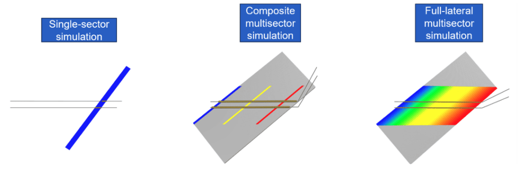
Again, because this is multisector, from the user-perspective, this all occurs within one simulation, in both setup and visualization.
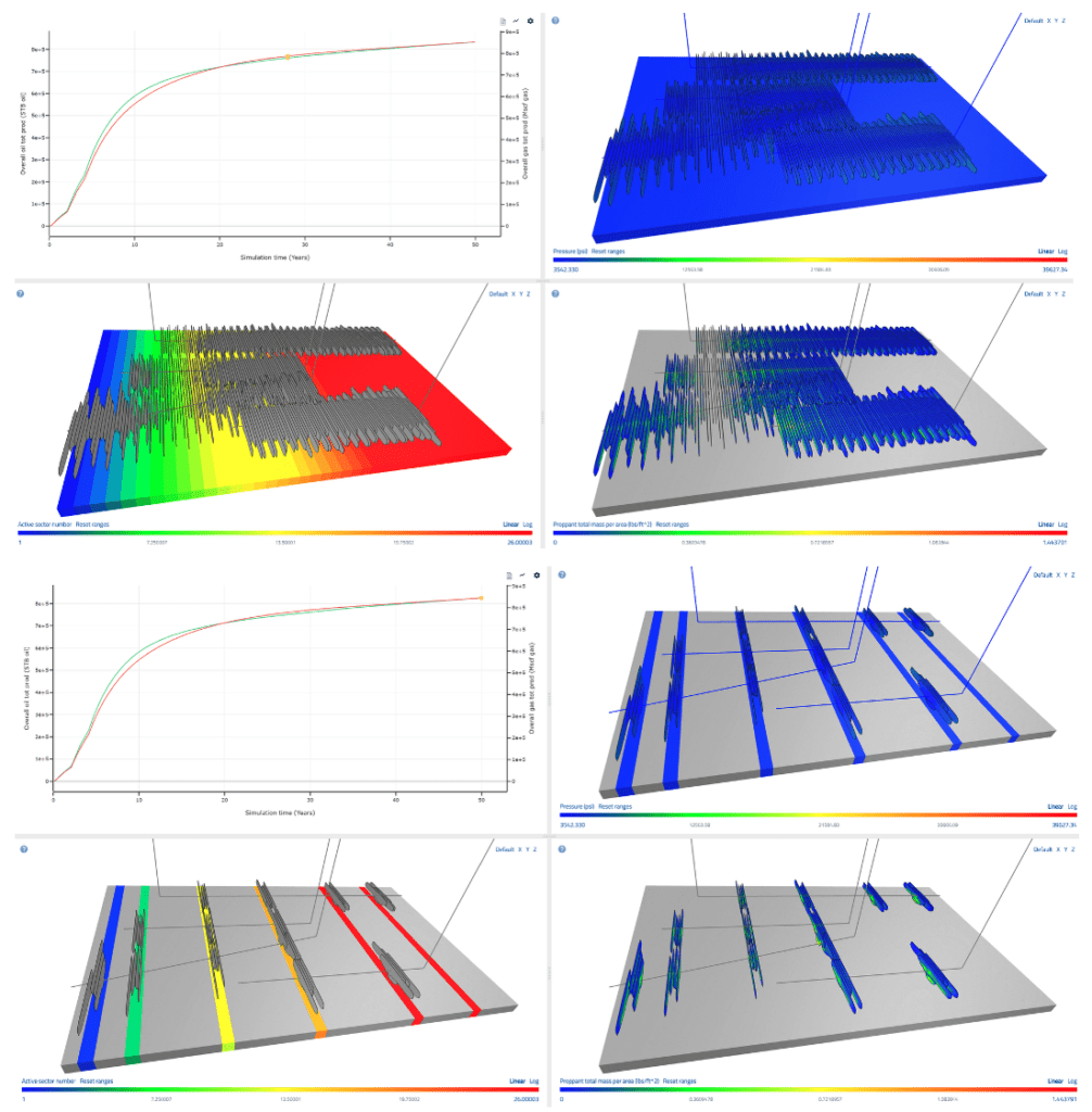
Here is a comparison between a full-lateral and a composite simulation. Because the sectors are scaled by relative contribution in the composite simulation, the resulting total production is similar in both cases. The composite model uses significantly fewer CPU hours.
Coupled multisector
Coupled multisector modeling was developed for cases that need to capture crossflow between stages. For example, during fluid circulation in EGS, pipe friction and heat conduction in the well need to be included in the model. We mesh the well to the surface and simulate flow from the injector wellhead, through the reservoir, and up to the producer wellhead. This can be done in a single sector simulation using so-called ‘well flow scalers’ to scale the flow rate in the wells. By scaling up the flow rate, the model can capture the ‘full rate’ effects of friction and heat conduction, even if we only model a fraction of the lateral (Singh et al., 2025).
Right now, we support only crossflow between sectors through the well. Crossflow through the matrix and fractures is not supported – the sector boundaries are no-flow. Because of this limitation, multisector cannot be used for all types of problems. Nevertheless, even with only crossflow through the well, we can unlock some very nice applications.
In coupled multisector, the timesteps of each sector model are synchronized. Fluid flows between the sectors, and each timestep is solved as a truly coupled single system of equations between all sectors. In other words, this is fully coupled distributed memory parallelization.
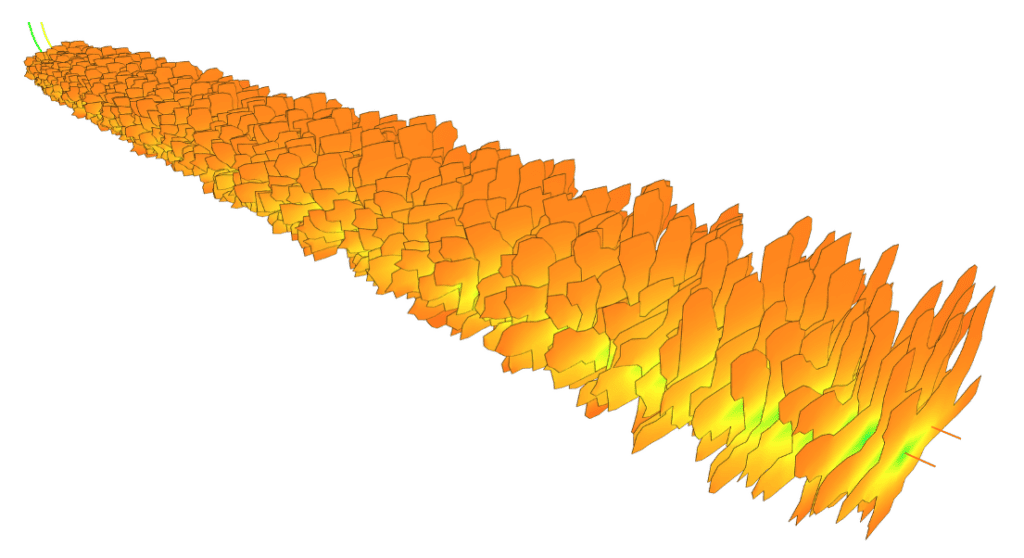
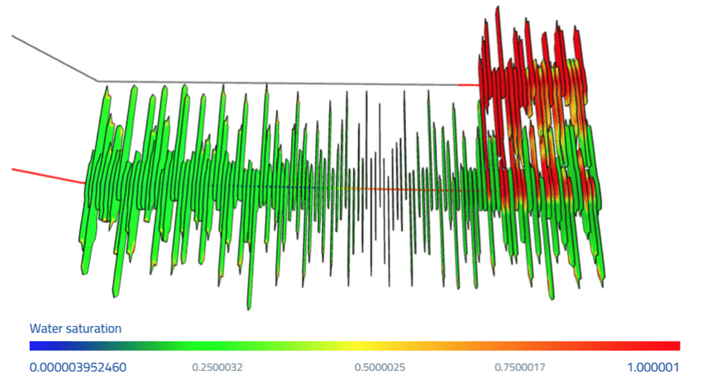
The schematic below shows how simulations can transition from uncoupled to coupled during an EGS simulation. During multistage fracturing, they run in uncoupled mode, gaining a huge speedup from running uncoupled for each stage during fracturing at the same time. Then, they come together and start running in coupled mode during the circulation period, when coupling is needed.

You can also use coupled to simulate frac hits during parent/child interaction. For most applications this is overkill. However, if you are doing a high-fidelity study on crossflow through the wells during frac hits, you could find this useful. In this sort of application, the simulation can go back-and-forth between coupled and uncoupled. The parent fracturing and production can be done uncoupled. The model switches to coupled to capture the complex effects of crossflow in the parent well during the frac hit, and then it switches back to uncoupled during long-term production. This is all seamless from the user’s perspective – it’s handled on the back-end.

Model setup
Setting up simulations with a large number of frac stages can be tedious. To address, we developed wizards to automate most of the multisector setup process. You start with a single sector model, and then the wizard converts it to a multisector model. The wizards performs a series of steps, such as setting up injection schedules and defining stages along the wells. You can prune the model back to be a composite model by specifying which stages to include in the simulation, which to omit, and how to scale the production from each active sector.
The wizard cannot account for every possible scenario that will be encountered by users ‘in the wild,’ but it is quite robust. It can handle wells with different lateral length, orientation, and even different stage length. As a user, if you have a complex situation that is not being handled by the wizard – let us know and we will help! And over time, we will keep adding to the wizard, based on user feedback.
Wrap up
How do you get started? We have prepared a variety of resources, which are provided in ResFrac’s documentation folder. You can access the “Overview of multisector modeling in ResFrac,” the “Multisector tutorial,” and the “Multisector user guide.” There are also two built in template simulations using multisector, “Bakken Multisector” and “Different Lateral Length MS.” Finally, there is a brief intro video below. And very important – please ask us for help! This is a brand new capability, and we’ve done a lot of testing and created a lot of help content. But we are sure there will be things we didn’t think of, and you’ll encounter situations where you’re not sure what to do next. Please ask us to help out!
Multisector puts a valuable tool in the ResFrac toolbox, allowing us to handle a variety of tricky practical situations that were previously inconvenient or impractical. Please enjoy!